What Are Traveling Block Components? This question reaches beyond a simple equipment checklist. Traveling Block Components form the moving lifting assembly above a drilling floor. They transfer hoisting power from the drawworks through the drilling line. Their movement raises or lowers the drill string, casing, and other heavy loads. A failure can stop operations quickly. It can also damage nearby equipment.
The main parts usually include the frame, sheaves, bearings, pins, guards, and hook connection. The sheaves guide the wire rope through carefully machined grooves. Bearings support rotation under substantial loads. The frame holds the assembly together during repeated movement. Pins and retainers secure critical connections. Small details matter. A loose guard, worn groove, or overheated bearing may reveal a larger maintenance problem. Experienced crews inspect lubrication, rope alignment, unusual vibration, and surface cracks before demanding heavy service.
Drilling equipment specialist Bill Mitchell offers a useful principle: “A lifting system is only as reliable as its weakest load path.” That idea explains why Traveling Block Components deserve practical, component-level attention. Manufacturers publish rated capacities, inspection intervals, and material specifications. Qualified technicians must compare those requirements with real operating conditions. Load cycles, corrosion, temperature, and handling habits can change performance. Still, no inspection plan is perfect. Human oversight can miss a developing defect. Records may also describe ideal conditions rather than difficult field work. This article examines each component, its function, common wear signs, and sensible maintenance practices. The goal is not merely identifying parts. It is understanding how each part supports safe, controlled, and dependable lifting.
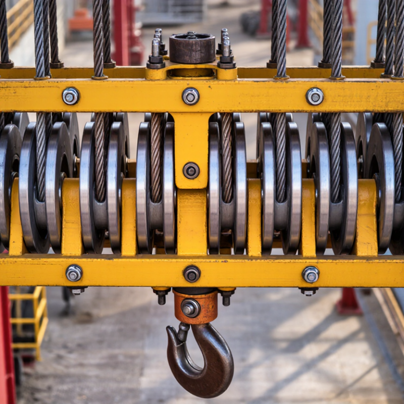
Traveling block components are the moving parts of a drilling rig’s hoisting system. The assembly usually includes a steel frame, multiple sheaves, bearings, pins, guards, and a connected hook. It travels vertically beneath the crown block. Together, these parts redirect wire rope and multiply lifting force.
The traveling block supports the drill string during lifting, lowering, and controlled positioning. Its sheaves must rotate smoothly as the wire rope passes through each groove. Bearings reduce friction, while pins and structural members transfer heavy loads through the frame. The hook connects the block to the equipment below. In practical operation, even a small groove defect can damage the rope and increase vibration.
Reliable performance depends on careful inspection and accurate maintenance records. Technicians commonly check sheave grooves, bearing temperatures, pin wear, lubrication points, and guard condition. They also compare observed wear with the manufacturer’s service limits and site procedures. I have found that visual checks alone can miss early bearing problems. Listening for uneven noise helps, but it is not enough.
A better inspection combines measurements, operating history, and experienced judgment. Still, no routine is perfect. Dust, poor lighting, or rushed shift changes can affect findings. That weakness deserves attention. Clear checklists and independent verification can reduce avoidable mistakes. When the traveling block is maintained correctly, it provides steady motion, controlled loads, and safer handling throughout drilling operations.
What Are Traveling Block Components?
Main Structural Parts of a Traveling Block
A traveling block carries the drilling load through a compact sheave assembly. Its main frame holds the sheave package, shaft, bearings, guards, and connection points. The sheaves guide drilling line between the crown block and the hook. Their grooves must match the line diameter. Poor matching can accelerate wear and create uneven loading.
The shaft supports rotating sheaves and transfers force into the frame. Heavy-duty bearings reduce friction, but they still need correct lubrication and clearance checks. The hook connection below the block transfers suspended weight to the drillstring. Guards protect personnel from moving line and rotating surfaces. It sounds simple. It is not.
API Spec 8C addresses design and rated-load requirements for drilling and well-servicing hoisting equipment. API RP 8B defines four inspection categories, from routine visual checks to major examination and testing. These categories help maintenance teams plan inspections by risk and equipment condition. Field technicians should record groove wear, bearing temperature, shaft condition, fastener security, and frame cracks. A 2024 international drilling activity report showed continued use of high-capacity rigs, increasing the importance of accurate load control. Yet inspection records are sometimes incomplete. That weakness deserves attention. A clean paint surface can hide fatigue, and a normal noise level cannot prove structural integrity.
A traveling block is a multi-sheave lifting assembly used in a drilling rig's hoisting system. The dimensions and ratings below represent common field ranges; exact values depend on the rated hook load, number of lines, sheave diameter, operating environment, and applicable lifting-equipment standards.
| Component | Primary Function | Typical Construction and Relevant Data | Inspection or Design Considerations | Relationship to Rated Capacity |
|---|---|---|---|---|
| Traveling-Block Frame | Supports the sheave assembly, bearings, guards, and load-transfer connections while moving vertically in the derrick or mast. | Fabricated or cast high-strength steel structure with side plates, cross-members, and reinforced lifting zones. Overall height commonly ranges from about 2 to 5 m, depending on sheave count and diameter. | Check welds, bolted joints, side-plate distortion, corrosion, lifting lugs, and clearance from the mast or derrick. | Must safely transmit the maximum static and dynamic hook load without permanent deformation. |
| Crown of Sheaves | Provides the grooved wheels that carry the drilling line and redirect its path between the drawworks and the crown block. | Usually includes 3 to 8 sheaves in conventional land-rig configurations. Sheave pitch diameters commonly fall in the approximate range of 0.9 to 1.8 m, with larger sizes used for heavier line and higher duty cycles. | Inspect grooves for wear, sharp edges, cracking, incorrect profile, and excessive fleet-angle effects. | Sheave diameter and groove geometry influence drilling-line bending fatigue and allowable line size. |
| Sheave Shafts | Carry the rotating sheaves and transfer radial and axial forces into the frame and bearing system. | Machined alloy-steel shafts, commonly heat-treated and fitted with shoulders, retaining arrangements, and bearing seats. Shaft diameter is selected from load, bending, fatigue, and bearing requirements rather than from a single standard value. | Check journals for scoring, fretting, wear, bending, cracks, and loss of interference or clearance fits. | Shaft strength must account for combined bending, shear, bearing reactions, and repeated cyclic loading. |
| Sheave Bearings | Allow the sheaves to rotate smoothly while carrying radial loads and, where applicable, axial or thrust loads. | Common arrangements use heavy-duty roller bearings, including spherical or cylindrical roller types. Bearing selection is based on dynamic load rating, speed, lubrication, contamination control, and service life. | Monitor temperature, noise, vibration, lubrication condition, seal integrity, and measurable radial play. | Bearing capacity and calculated fatigue life must be compatible with the block's rated hook load and duty cycle. |
| Sheave Grooves | Guide the drilling line and distribute contact pressure over the rope surface. | Grooves are machined or fitted with replaceable liners. Groove profile and pitch diameter must match the nominal drilling-line diameter; a frequently used design principle is a sheave-to-rope diameter ratio of approximately 18:1 or greater for reducing bending fatigue. | Measure groove depth and contour using approved gauges; inspect for polishing, ridges, peening, cracks, and uneven wear. | Incorrect groove geometry can reduce rope life and may compromise the effective lifting performance of the hoisting system. |
| Sheave Guards and Line Retainers | Help prevent the drilling line from climbing out of the grooves and protect personnel from rotating components. | Constructed from steel plate, bars, or guards with controlled clearances. Designs generally provide access for inspection while limiting contact with moving sheaves and rope. | Verify secure attachment, correct clearance, absence of sharp edges, and freedom from deformation or interference with the rope. | Normally not the primary load-bearing element, but failure can create a serious rope-derailment and personnel hazard. |
| Hook-Suspension Connection | Connects the traveling block to the hook or hook block and transfers the lifted load to the drill string, casing, or other suspended equipment. | May use an integrated hook-support arrangement, load shoulders, pins, links, or a separate hook block, depending on the rig design. Components are typically forged or heat-treated alloy steel. | Inspect load-bearing surfaces, pins, retainers, links, safety latches, thread areas, and evidence of impact or bending. | Every connection in the load path must have a rated capacity at least equal to the applicable system rating. |
| Lubrication and Sealing System | Reduces friction and wear in bearings, shafts, and rotating interfaces while limiting entry of water, drilling fluids, and abrasive contaminants. | May include grease passages, oil reservoirs, seals, shields, breathers, and drain arrangements. Lubricant type and quantity are selected for bearing design, ambient temperature, rotation speed, and contamination level. | Check for leaks, blocked passages, degraded seals, water contamination, overheating, and incorrect lubricant mixing. | Insufficient or contaminated lubrication can sharply reduce bearing life and may lead to unplanned loss of lifting capability. |
| Identification and Load-Rating Plate | Displays essential information needed for safe operation, inspection, and maintenance. | Normally identifies rated capacity, serial or equipment identification, applicable design standard, sheave arrangement, and required inspection information. Rating is commonly expressed in tonnes or kN. | Ensure markings remain legible and correspond with current inspection records, certificates, and rig operating procedures. | The marked rating is the governing limit; the lowest-rated component in the complete hoisting load path may control the allowable working load. |
Note: Values shown are representative engineering ranges, not a substitute for the manufacturer's certified drawings, load charts, inspection criteria, or the requirements of applicable lifting and drilling-equipment standards.
Traveling block components work as one load-handling system. The frame supports multiple sheaves, which guide the wire rope through repeated passes. Bearings let each sheave turn smoothly under pressure. A central hook transfers the lifted load to the connection below. Guards, pins, and fasteners keep these parts aligned during movement.
The system depends on balance. Each sheave must rotate freely, while the rope must sit correctly inside every groove. Uneven wear can increase friction and create heat. A loose pin may shift the frame slightly, changing the rope path. That small change can affect lifting efficiency and safety. Practical inspections should check cracks, damaged grooves, bearing noise, hook deformation, and missing securing devices. A clean exterior can mislead. Internal wear is easy to overlook.
Tips: Keep the block clean and dry after use. Compare rope wear across every sheave. Listen for rough movement during a slow test. Record inspection dates and unusual findings. Never exceed the rated working load. A qualified inspector should assess serious damage before the block returns to service. Maintenance routines are not perfect, and rushed checks happen, but a written checklist helps reveal those weak moments.
A traveling block is a movable pulley assembly used in drilling and lifting systems. It carries heavy loads through multiple sheaves and wire rope lines. Core components include the frame, sheaves, shafts, bearings, pins, guards, and lubrication points. Each part must work smoothly under repeated loading.
Manufacturers commonly use forged alloy steel for shafts, pins, and load-bearing frames. Sheaves may use specially treated steel to resist groove wear and rope damage. Heat treatment improves strength, but it does not remove every risk. Poor lubrication, misalignment, and hidden cracks can still shorten service life.
Design work should follow recognized lifting and drilling standards, such as API requirements where applicable. Engineers check rated hook load, line pull, reeving arrangement, and dynamic effects. The safe working load must match the weakest connected component. A block rated for a high static load may perform differently during sudden starts or stops.
Field inspections should measure groove wear, bearing temperature, side-plate distortion, and pin condition. Non-destructive testing can reveal cracks that visual checks miss. Load capacity calculations also need accurate rope size and fleet angle data. Records are sometimes incomplete. That uncertainty deserves a conservative engineering decision, not a guess. A practical review compares design documents with inspection findings and real operating history.
What Are Traveling Block Components?
A traveling block carries the drilling load through several sheaves, bearings, a frame, guards, and connecting hardware. Each part needs a different inspection approach. Sheave grooves should be checked for sharp edges, uneven wear, and rope tracking marks. A groove that looks acceptable may still damage wire rope under heavy load.
Inspect bearing housings for rising temperature, unusual vibration, and grease leakage. Small noises matter. Compare readings with earlier records instead of relying on touch alone. Check bolts, pins, guards, and locking devices for looseness or distortion. The frame deserves close attention around welds, corners, and load-bearing joints. Use approved procedures to isolate and secure the equipment before hands-on work begins.
Maintenance should follow the service manual, site conditions, and inspection history. Lubricate with the specified product and quantity. Excess grease can hide contamination or create heat. Measure sheave alignment and groove condition when rope wear appears repeatedly. Common failures include seized bearings, cracked sheaves, worn grooves, loose fasteners, and damaged guards. Overloading or poor alignment often accelerates these problems. A clean exterior can mislead. Experienced crews still miss defects when inspections become routine. I would also question replacement decisions based only on appearance; measured wear, vibration trends, and load history provide stronger evidence. Document every finding, including minor changes, because small deviations often appear before serious failure.
It is a moving pulley assembly in a drilling rig’s hoisting system. It travels vertically beneath the crown block. Its sheaves redirect wire rope and increase lifting force.
Common parts include a steel frame, sheaves, bearings, shafts, pins, guards, and a connected hook. Lubrication points are also important. Every part transfers or controls heavy loads.
It supports the drill string during lifting, lowering, and positioning. Multiple sheaves spread the load across several rope lines. Smooth movement helps control heavy equipment.
Load-bearing frames, shafts, and pins commonly use forged alloy steel. Treated steel is often used for sheaves. Heat treatment improves strength, but it cannot prevent every failure.
Engineers consider hook load, line pull, rope size, reeving, fleet angle, and dynamic effects. The safe working load must match the weakest connected component. Sudden starts can create higher forces than steady lifting.
Check sheave grooves for sharp edges, uneven wear, and rope tracking marks. Measure bearing temperature and listen for unusual noise. Inspect pins, bolts, guards, welds, corners, and locking devices.
Visual checks may miss early bearing problems or internal cracks. Temperature readings, vibration trends, measurements, and non-destructive testing provide stronger evidence. A clean surface can mislead.
Follow the service manual, site procedures, and inspection history. Use the specified lubricant and quantity. Excess grease may hide contamination or create heat.
Common problems include seized bearings, cracked sheaves, worn grooves, loose fasteners, and damaged guards. Overloading and misalignment can accelerate damage. Small changes often appear before serious failure.
Records show whether wear, temperature, or vibration is increasing. They also support replacement decisions based on evidence. Rushed inspections still happen, so independent verification deserves attention.
Traveling Block Components are the essential parts of a drilling hoisting system that help raise, lower, and support heavy loads safely and efficiently. A traveling block typically includes a frame, sheaves, bearings, shafts, guards, and connection points. These parts work together with the fixed equipment above the well to guide the lifting line, distribute loads, and control vertical movement during drilling or related operations.
The design of Traveling Block Components depends on material strength, engineering standards, operating conditions, and rated load capacity. Proper inspection and maintenance are necessary to identify wear, cracks, corrosion, bearing damage, loose fasteners, or uneven sheave movement before they become serious problems. Regular lubrication, alignment checks, cleaning, and accurate load monitoring can extend service life and improve reliability. Understanding each component and its role helps operators maintain safe performance and respond quickly to common failure issues.

MTPM RigParts